Since the Bushmaster 2000 is an electro-pneumatic
marker, it requires
circuitry to control the firing cylce.
The following describes the Bushmaster 2000 circuit.
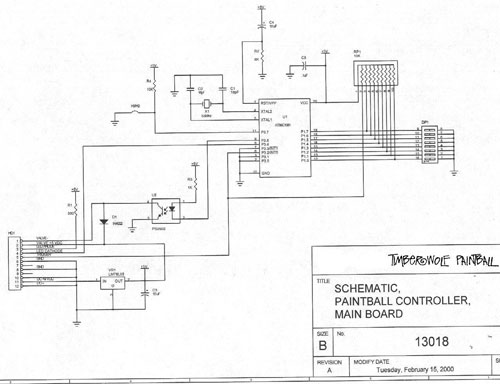
The heart of the circuit is the integrated circuit (IC) chip.
This IC is a microcontroller which comprises input/output logic,
a processing unit, and non-volatile memory. This memory contains
a program that controls the mode of fire and the solenoid timing.
The IC receives input from the DIP switches and tailors the
program to produce the desired results. A resistor pack is used
to ensure that the IC inputs are set to a strong logical high
or 5V signal. Upon throwing a DIP switch, the IC input is pulled
to a logical low or to 0V. Since the circuit must operate on
5V DC, the voltage regulator reduces the voltage supplied by
the 9V battery to 5V DC. This supply is applied to the VCC input
of the IC and is cleaned by a capcitor to protect the IC. The
two capacitors tied to the crystal are used in conjuction with
the internal crystal input circuit of the IC to produce the
timing function. When the IC receives a fire signal from the
micro-switch contacted by the trigger, it starts the firing
sequence. The IC produces a signal intended to change the state
of the solenoid to fire the marker. In order to protect the
IC from dangerous inductive charges produced by the solenoid,
a diode is placed across the solenoid coil. Additionally, an
opto-coupler is placed between the IC and the solenoid. The
IC signal turns on the light emitting diode internal to the
opto-coupler. The receiver inside the opto-coupler detects the
light and completes the circuit to provide a 5V signal to the
solenoid. Timing parameters determined by the DIP switches causes
the IC to cease the solenoid signal and return the solenoid
to the ready state.